Microstructure Effects on Hydrogen Embrittlement in Austenitic Steels: A Multidisciplinary Investigation

Fig.1: Detecting hydrogen on a 50×50 µm² surface area of a H charged austenitic steel after evaporation of a 100 nm Pd film. a) A topographic image obtained by AFM indicates austenitic (due to surface preparation topographically higher) and ferritic (lower, i.e., darker) regions. b) and c) Potential maps of this area obtained after 28 h and 44 h in the Kelvin probe mode. Above the austenites the potential decreases faster than above the ferrites due to the larger amount of stored hydrogen. The dark spots in b)-c) indicate sites with especially high hydrogen concentrations (traps).
© Max-Planck-Institut für Eisenforschung GmbH
 grain boundary in fcc iron. The minimum energy path for a diffusion in a (1-10) / (113) plane perpendicular / parallel to the boundary is indicated by white dots. In the upper part the corresponding energies along the same path are plotted.](/3746593/original-1518437952.jpg?t=eyJ3aWR0aCI6OTY2LCJvYmpfaWQiOjM3NDY1OTN9--b5480f11b5b03d216088857f1f169af1e542aa64)
Fig. 2: Potential energy surface for a single H interstitial next to a Σ11[1-10](113) grain boundary in fcc iron. The minimum energy path for a diffusion in a (1-10) / (113) plane perpendicular / parallel to the boundary is indicated by white dots. In the upper part the corresponding energies along the same path are plotted.
© Max-Planck-Institut für Eisenforschung GmbH

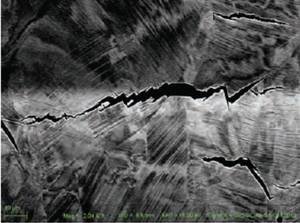
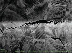
Fig. 3: ECCI micrograph for the crack propagation in Fe–18Mn–1.2C austenitic steel. The cracks initiate at a grain boundary, where deformation twins are intercepting. The crack propagation afterwards continues along the deformation twins.
© Max-Planck-Institut für Eisenforschung GmbH
Ceylan Senöz, Stefan Evers, Martin Stratmann, and Michael Rohwerder, "Scanning Kelvin Probe as a highly sensitive tool for detecting hydrogen permeation with high local resolution," Electrochemistry Communucations 13 (12), 1542-1545 (2011).
Stefan Evers and Michael Rohwerder, "The hydrogen electrode in the “dry”: A Kelvin probe approach to measuring hydrogen in metals," Electrochemistry Communications 24, 85-88 (2012).
In preparation
Y. J. A. Du, L. Ismer, J. Rogal, T. Hickel, J. Neugebauer, and R. Drautz, "First-principles study on the interaction of H interstitials with grain boundaries in alpha- and gamma-Fe," Physical Review B 84 (14), 144121-1-144121-13 (2011).
Hydrogen-induced cracking at grain and twin boundaries in an Fe–Mn–C austenitic steel
Scripta Materialia 66 (2012), 459-462

 grain boundary in fcc iron. The minimum energy path for a diffusion in a (1-10) / (113) plane perpendicular / parallel to the boundary is indicated by white dots. In the upper part the corresponding energies along the same path are plotted. Fig. 2: Potential energy surface for a single H interstitial next to a Σ11[1-10](113) grain boundary in fcc iron. The minimum energy path for a diffusion in a (1-10) / (113) plane perpendicular / parallel to the boundary is indicated by white dots. In the upper part the corresponding energies along the same path are plotted.](/3746593/original-1518437952.jpg?t=eyJ3aWR0aCI6MzQxLCJmaWxlX2V4dGVuc2lvbiI6ImpwZyIsIm9ial9pZCI6Mzc0NjU5M30%3D--32927360a739b1fc2c48fb2d2895e50b87fc63c6)
