5. Displacive phase transformations in CPFE modeling

5.1. Introduction

The preceding sections focused on dislocations as carriers of plastic shear. However, materials such as austenitic steels, TRIP steels (TRIP: transformation induced plasticity), brass, TWIP steels (TWIP: twinning induced plasticity), and shape memory alloys, deform not only by dislocation slip but also by displacive deformation mechanisms (also referred to as displacive transformations). These mechanisms are characterized by a dffusionless collective motion of clusters of atoms where each atom is shifted only by a small distance relative to its neighbors. Such transformations create shears with kinematics similar to that of dislocations. Two such mechanisms and their incorporation into the CPFE framework will be discussed here, namely, martensite formation [74, 80] and mechanical twinning [164, 165, 166, 169]. Martensite formation takes place by a shear-induced change of the crystal structure which, as a rule, involves a volume change. Mechanical twinning proceeds by a shear mechanisms which reorients the volume affected into a mirror orientation relative to the surrounding matrix. We discuss how the CPFE approach can be modified to include these mechanisms and how the interactions among the competing shear carriers can be considered in the constitutive formulations.

5.2. Martensite formation and transformation-induced plasticity in CPFE

The presence of metastable retained austenite grains is responsible for the strength–ductility characteristics of transformation-induced plasticity (TRIP)assisted multiphase steels [250]. Upon mechanical and/or thermal loadings, retained austenite may transform into martensite and generate the TRIP effect. The investigation of the TRIP effect was initiated by Greenwood and Johnson [251] in 1965, where in a test specimen, irreversible plastic deformations were observed at a stress lower than the theoretical yield stress of the material. It has been suggested that the additional plastic deformation of the material is induced by the volumetric growth accompanying the transformation of retained austenite into martensite (see, e.g., Fischer et al. [252]). In the same year, Patel and Cohen [253] observed that during transformation, martensite develops in a preferred orientation that maximizes the transformation driving force.

Wechsler et al. [254] proposed a crystallographic model for the kinematics of martensitic transformations. This concept was refined by Ball and James [255], who further developed the modeling concept within the energy minimization landscape. During the last decades, various constitutive models for martensitic transformations have been proposed, such as the onedimensional model of Olson and Cohen [256], which was extended into a three-dimensional model by Stringfellow et al. [257]. Lately, more complex micromechanical models were proposed, e.g., [83, 258, 259, 260, 67, 68, 69, 75, 70, 71, 72, 73, 261, 262], which have been used in particular for simulating TRIP steels. However, the models mentioned above have some drawbacks, i.e., most of them were derived for a small-strain framework This can lead to inaccurate predictions as martensite transformations induce locally large elastic and plastic deformations, even if the effective macroscopic deformation is relatively small. Furthermore, an isotropic elasto-plastic response is often assumed. This constraint is quite strong, especially at the single crystal scale, where the effect of crystallographic anisotropy cannot be neglected.

The following sections present the development of a crystallographicallybased thermo-mechanical model for simulating the behavior of multiphase TRIP-assisted steels. The austenitic phase is described by a single crystal elasto-plastic-transformation model.

The phase transformation model of Suiker and Turteltaub [263, 78, 234] is applied to simulate the transformation of face-centered cubic (fcc) austenite into body-centered tetragonal (bct) martensite. This model is developed within a multi-scale framework and uses the results from the crystallographic theory of martensitic transformations [254, 255]. The martensitic transformation model is coupled to a single crystal plasticity model for fcc metals in order to account for plastic deformation in the austenite. The coupling between the transformation and plasticity models is derived using a thermodynamically-consistent framework.

5.2.1. Decompositions of deformation gradient and entropy density

The total deformation gradient F and the total entropy density η can be decomposed into the elastic, plastic and transformation parts, in accordance with:

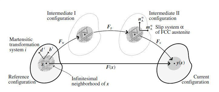
where Fe, Fp, and Ftr are, respectively, the elastic, plastic and transformation contributions to the total deformation gradient, while ηe, ηp, and ηtr are, respectively, the reversible part of the entropy density, the entropy density related to the plastic deformation, and the entropy density associated with the phase transformation, figure 13.

The transformation part of deformation gradient, Ftrentropy density, and the transformation ηtr, are, respectively, given by

where vectors bi and di are, respectively, the transformation shape strain vector and the normal to the habit plane of transformation system i (measured in the reference configuration. I is the second-order identity tensor, θtr is the (theoretical) transformation temperature, at which transformation occurs instantaneously at zero stress (no energy barrier, no dissipation), and λitr is the latent heat of a transformation system i, which measures the heat required per unit mass during a complete transformation at the transformation temperature θtr. In the expressions (46), ξi represents the volume fraction of martensitic transformation system i measured in the reference configuration, which satisfies the following requirements:

with ξA the volume fraction of the austenite measured in the reference configuration. In the case of the transformation from fcc austenite to bct martensite, the total number of possible transformation systems is M = 24.

It is assumed that dislocation plasticity only occurs in the austenite but not in the martensite owing to its high yield resistance. Furthermore, plastic deformations that occurred in the martensitic sub-domains prior to transformation (if any) are assumed to be inherited to the martensitic phase. Accordingly, the evolution of the plastic deformation gradient Fp (given in terms of the plastic velocity gradient Lp) and of the plastic entropy density ηp are, respectively, described by (in rate forms)

where the vectors mαA and nαA are, respectively, unit vectors describing the AA slip direction and the normal to the slip plane of the corresponding system in the fcc austenite, measured in the second intermediate configuration, and φαA is interpreted as the entropy density related to plastic deformation per unit slip in system α. In the above expressions, ˙γα can be interpreted as the “effective” plastic slip rate of the austenitic slip system α, which is given by γ˙α = ξAγ˙αA/Jtr, with ˙γα the rate of slip on a system α in the austenite and Jtr = det Ftr.

5.2.2. Constitutive relations of stress-elastic strain and temperature-reversible entropy

The constitutive relations between conjugated variables, i.e., stress-elastic strain and temperature-reversible entropy, are defined by

where S is the second Piola–Kirchhoff stress in the second intermediate configuration, which is conjugated to the elastic Green–Lagrange strain, Ee, θ is the temperature and ηrev is the reversible entropy measured at the transformation temperature, i.e., θ = θtr. Furthermore, the effective elasticity tensor C and the effective specific heat h comprise the contributions from the elastic stiffness and the specific heat of the individual austenitic and martensitic phases, i.e.,

where δtr = bi · di gives the volumetric growth associated with each transformation system i, which is constant for all i =1,..., M. Note that the effective elasticity tensor C and the effective specific heat h evolve with the martensitic volume fractions ξi during transformation.

5.2.3. Driving forces and kinetic relations for transformation and plasticity

The driving force for the phase transformation, denoted as fi, can be written as

where fim , fith , fid and fis summarize, respectively, the mechanical, thermal, mth, fd i s defect, and surface energy contributions to the transformation driving force. The mechanical part of the transformation driving force, fim, is computed as

which comprises the contribution of the resolved stress and the elastic stiffness mismatch between the martensite product phase and the austenite parent phase with stiffness CA. The thermal part of the transformation driving force, fith , describes the contribution of the transformation latent heat as well as the mismatch of the specific heat between martensite and austenite, i.e.,

with ρbeing the mass density in the reference con guration. The defect and surface energies contributions are, respectively, given by

with ωA a scaling factor for the defect energy, β the microstrain parameter related to the density of dislocations in the austenitic/martensitic region, χ an interfacial energy per unit area and l0 a length-scale parameter representing the volume-to-surface ratio of a circular platelet of martensite within a spherical grain of austenite. In equation (54)2, µA and µi represent the (equivalent) shear moduli of the austenite and martensitic system i, respectively. The evolution of the martensite fraction during transformation follows the rate-dependent kinetic formulation:

where ficr stands for the critical value of the transformation driving force. The parameters ξ˙0 (maximum transformation rate) and ν (viscosity-like parameter) determine the rate-dependence of the transformation kinetic law.

The driving force, gαA, for plastic slip in the austenitic phase is obtained from the thermodynamic formulation as

where µ is the effective shear modulus, which is computed using a similar technique as used for the effective elasticity tensor, i.e.,

Furthermore, wα is a function that relates the rate of microstrain β to the plastic slip rates γα as β = ∑Nα=1wαγα. Finally, the evolution of plastic slip in the austenitic phase is described using a power-law kinetic relation in the form

where sAα is the resistance against plastic slip in system α. The evolution of the slip resistance is described through a hardening law where ˙γ0A and mA are the reference slip rate and the rate-sensitivity exponent, respectively. More details on the austenite elasto-plastic-transformation model can be found elsewhere [82].

For simulating the behavior of multiphase TRIP-assisted steels, a ratedependent crystal plasticity model is additionally applied for the ferritic phase. Similar to the austenite elasto-plastic-transformation model, the kinematics of the model is constructed within a large deformation framework where the total deformation gradient is multiplicatively decomposed into elastic and plastic deformation gradients. Most of the formulation for the ferrite can be derived in a similar way as for the elasto-plasto-transformation model of the austenite, but without the transformation contribution.

Moreover, at the atomic scale, the plastic deformation in bcc metals involves complex mechanisms due to the non-planar spreading of the screw dislocation cores [264, 265]. In order to take these effects into account, the approach of Bassani et al. [266] and Vitek et al. [267] is adopted, where the effect of non-glide stress is incorporated in the model by modifying the critical resolved shear stress according to

where ˜αα is a coefficient that gives the net efect of the non-glide stress on the effective resistance, and ˜ταF is the non-glide stress of slip system α, given by

The kinetic law is constructed through inserting the modified critical Schmid stress instead of the classical slip resistance into a power-law expression for the plastic slip rate. More details on the model for the bcc ferrite are in [268, 82].

5.3. Mechanical twinning in CPFE models

Arbitrary permanent changes of shape of a single crystal require the operation of any five linearly independent shear systems [4]. However, the number of easily activated slip systems of a given crystal structure may be insuffcient to fulfill this requirement. Thus alternative displacive modes, e.g. mechanical twinning, can also participate in the overall plastic deformation. Low-symmetry crystal structures, e.g. hexagonal crystals with large c/a are typical examples for this situation. Also, cubic metals may exhibit mechanical twinning due to a relatively strong increase in the critical shear stress at low temperatures and the rate dependence of slip in the case of bcc materials and due to the low value in the stacking fault energy in the case of fcc materials [269]. A mechanical twin formally corresponds to a sheared volume for which the lattice orientation is transformed into its mirror image across a so-called twin/composition/habitus plane, figure 14. A vector of the initial lattice is moved into its new position in the twin through a transformation/rotation matrix Q. The same expression for Q was derived for bcc and fcc twins [270, 269], exploiting the equivalence of rotating half of the crystal by an angle π either around the twin direction or around the twin normal

where n is the twin plane unit normal and δij Kronecker’s symbol. Alternatively, twinning can be viewed as unidirectional shear on the habitus plane, i.e. formally similar to bidirectional dislocation slip. In this framework, fcc twins are of type {111}(112), bcc twins of type {112}(111), and hcp twins of type {10¯12}(10¯11) Although strain-induced twinning has been investigated for years [271], most of its governing physical mechanisms still remain unclear. Numerous studies aimed at identifying the influence of the boundary conditions on mechanical twinning, placing attention on temperature, grain size, and stacking fault energy and their respective influence on twin nucleation and growth. Some of the results which are required for deriving corresponding micromechanical models, are summarized in the following.

Temperature and strain rate
In most crystal structures twinning gains relevance as the temperature is lowered and/or the strain rate increased. The temperature dependence is often explained by the fact that the flow stress increases steeply with decreasing temperature (in bcc metals), so that finally the twin stress is reached [269]. The temperature dependence of the twin stress is under debate in the literature. Bolling and Richmann [272] and Koester and Speidel [273] found a negative temperature dependence of the twinning stress in fcc crystals while Mahajan and Williams [274] suggested for the same structure the opposite trend. Contradictory observations have also been reported for other crystal structures, so that the current state of knowledge seems insuficient to reach a definitive conclusion, as pointed out by Venables [275]. Only a few investigations have addressed the strain ratedependence on the twinning stress [276, 277, 278].

Grain size
Armstrong and Worthington [279] were the first to propose a link between the increase in the twinning stress and the decrease of the grain size by means of a Hall–Petch-type relation. Later experimental studies on different materials and structures [280, 281, 282, 283] supported this suggestion. It is worth noting that the so-called twin slope, i.e. the dependence of twin activation on the grain size, is often found to be much higher than the corresponding slope for dislocation slip [279].

Stacking fault energy
It is well established that twinning occurs preferentially in low stacking fault energy materials. With decreasing stacking fault energy it is easier to separate partial dislocations from each other. This leads to a wider stacking fault which may eventually trigger a deformation twin. Concerning the effect of other parameters it was proposed that the stacking fault energy increases with increasing temperature [284]. This might explain the apparent temperature dependence of mechanical twinning. Alternatively, the notion of an effective stacking fault energy was introduced in order to consider the effect of the orientation on the splitting length between partial dislocations [285, 286].

The preceding list of relevant parameters affecting mechanical twinning is of course not complete since other factors such as chemical composition, strain and stress state, and precipitates also influence strain-induced twinning [271].

The motivation for modeling mechanical twinning in a CPFE framework echoes practical as well as fundamental demands. Interest in twinninginduced plasticity (TWIP) steels has grown rapidly over the last years as these grades simultaneously provide high strength and good ductility. Similar aspects hold for stainless steels, magnesium alloys, and some intermetallic compounds where deformation twinning plays a role. In each of these cases an interest exists to predict the mechanical response, the microstructure evolution, and the texture by using advanced CPFE models.

To our knowledge, the first phenomenological introduction of mechanical twinning into the CPFE framework was accomplished by Doquet [287], followed by Schl¨ogl and Fischer [288] and Mecking et al. [289]. The corresponding implementation into a finite element scheme was proposed by Kalidindi [164, 114] and further developed in [290].

5.3.1. A modified CPFE framework including deformation twinning

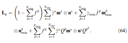
The CPFE framework discussed in this section follows the outline introduced above. However, adding mechanical twinning as a possible plastic shear mode requires introduction of some additional model ingredients. The activation of a twin system β implies that a fraction dfβ of the single crystalline parent volume (matrix) reorients by Qβ . Figure 15 illustrates the decomposition of the global deformation gradient F when a twin system operates. Considering the formal similarity between slip and mechanical twinning, the velocity gradient Lp is extended by the contribution due to the characteristic twin shear γtwin, e.g. √2/2 for fcc and bcc crystal structures

where Nslip is the number of slip systems and Ntwin the number of twin systems. It should be noted that the present description does not explicitly account for the morphology and topology of the deformation twins. Instead a twinned region is specified by its volume fraction and by the boundary condition that no explicit plastic deformation gradient is prescribed within twinned regions. The Cauchy stress σ¯of the composite, i.e. matrix plus twins, is related to the volume average of the stress over all constituents:

where Cβijkl = Qβim Qβjn Qβko QβlpCmnop is the elasticity tensor of the matrix rotated into the respective twin orientation and Ee the Green–Lagrange strain derived from the non-plastic deformation gradient Fe. It is worth noting that a small homogenization error may occur when following this procedure, which is due to the generation of an orientation dispersion in the twinned fraction. This deviation occurs whenever the plastic spin of a twin variant is not equal to the plastic spin of the matrix. In the current case this effect does indeed take place because no plastic velocity gradient is given in the twinned regions.

The present expression for Lp does not consider subsequent dislocation slip within twins. This approximation is often suitable for extremely thin fcc and bcc twins. However, experimental evidence for dislocation activity in mechanical twins has been reported when twins are larger, e.g. in highmaganese TWIP steels [291] (due to large strains) and in hexagonal metals (Mg, Zr due to small twin shear). It may, therefore, be useful to allow for dislocation slip in twinned regions. In that case, Kalidindi [114] proposed to modify the plastic velocity gradient as follows

Furthermore, secondary twinning, i.e. the twinning of primary twins, might be considered as well. At first view the modification of Lp appears rather straightforward. However, diffculties arise from the increase in the number of shear rates or twin volume fractions that have to be handled in this approach, rendering the model highly impractical. The time-integration scheme, presented in section 8, remains essentially unchanged. The non-linear equation is still expressed in terms of the second Piola–Kirchhoff stress tensor, written in the intermediate configuration, for a given microstructure, i.e. for state variables that refer to both slip and twinning. Details on the numerical implementation can be found elsewhere [109].

5.3.2. Phenomenological Approach to Mechanical Twinning

The plastic velocity gradient is defined in terms of all shear rates ˙γα and all volume fractions created by the twinning rates f˙β. Phenomenological expressions of the shear rate on a slip system have been introduced above. However, no theory is currently available to provide a clear function for the evolution of the twinned volume fraction for an active twin system. For this reason Kalidindi [164] proposed to use the analogy between slip and twin systems while preserving the unidirectionality of the twinning mechanism. The twin volume fraction of a system β then evolves according to a phenomenological power-law equation:

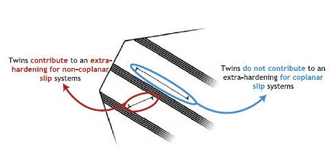
The computation of this flow rule requires the specification of a critical twinning shear stress (shear resistance) τcβ for each twin system. This is a critical point since experimental observations support the idea that mechanical twins have a ”double” impact on the global strain hardening of the material. First, an increasing amount of twins leads to an increasing hardening effect on slip systems since moving dislocations stop at twin-matrix interfaces. This concept is illustrated in figure 16 for the fcc case. A moving matrix dislocation will most likely encounter twins that lie on planes that are non-coplanar with its glide plane, i.e. only non-coplanar twin systems act as obstacles for dislocation motion. Second, the production of new twins is impeded by already existing twins, which is referred as the hardening behavior for the respective twin systems. Following the first idea, Kalidindi proposed to modify the phenomenological slip hardening rule according to

where the hardening matrix  now depends on the twin volume fractions through the saturation value τsα:

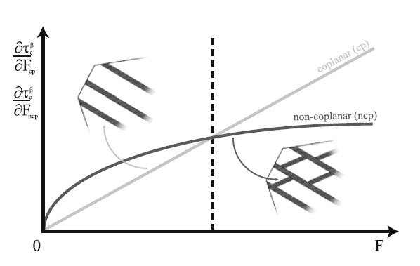
Dislocations tend to accumulate before twin boundaries, which justifies the changes in the saturation value for the slip resistances. The Hall–Petch-like formulation that quantifies the contribution due to deformation twinning in the saturation value is derived naturally from the analogy with grain boundary hardening. It is worth noting that some later works [169] suggest not only modifying the saturation values but also h0 in order to account for the Basinski effect [169, 292]. The second idea refers to a kind of ”twin–twin” hardening behavior of the material and originates from the sequential activation of twin variants during deformation. It was often observed that in fcc metals only coplanar twins form at first in a grain. Upon a strain threshold, deformation twins, that are non-coplanar with the first ones, form, leading to a ladder-like microstructure. This sequential activation, described in figure 17, is phenomenologically translated in terms of two monotonic mathematical power functions depending on either strain rate [169] or twin volume fraction rates [114]. The two functions cross at a given point. Below that point, existing twins preferentially harden non-coplanar twin systems. Beyond that point, existing twins preferentially harden coplanar twin systems. This model approach is easy to handle and has been successfully applied to α-brass [114], α-Ti [169], and TiAl [288].

Figure 17: Sequential activation of twin systems and its mathematical/numerical treatment for fcc structures: at small strains, the hardening evolution of existing twins is mainly governed by the activity of noncoplanar twins. Beyond a critical point, existing twins are strongly hardened by coplanar twins, phenomenologically triggering formation of non-coplanar twins. ( critical twinning shear stress, F, Fcp, Fncp: cumulative twin volume fraction of all twin systems, only those systems which are co-planar, and those which are non-coplanar to system b, respectively.

5.4. Guidelines for implementing displacive transformations in CPFE constitutive models

This section discussed the basic constitutive and kinematic ingredients for implementing displacive shear mechanisms as additional carriers of crystallographic plastic deformation in CPFE frameworks. The challenges of rendering such models physically sound and at the same time numerically tractable seem to lie in two areas. The first one is the appropriate formulation of nucleation and growth models. The second one is the identification of appropriate homogenization methods. The first point means that nucleation and growth models should be designed in a way to capture the basic dependence of displacive transformations on thermodynamic and microstructural parameters such as temperature, grain size, strain rate, and stacking fault energy. The second point refers to the desired level of discretization. This means that in some cases multiple and repeated transformations may occur at the same integration point. This requires defining an adequate approach for tracking and homogenizing the volume portions and interaction mechanisms for different twin or martensite lamellae or corresponding higher order transformations (e.g. twinning of twins), see Figure 4b.

Go to Editor View