
9. Experimental validation and application
9.1. Introduction
CPFE simulations can be validated by experiments in a detailed way, with respect to both mechanical and microstructure observables. Measures of the former group can be monitored in terms of forces, elastic stiffness (including springback effects), stresses, mechanical size effects, mechanical anisotropy, shape changes, hardness, strain paths, strain rates, and strains including local strain maps obtained by digital image correlation or speckle methods. Quantities based upon microstructure observations can be mapped in terms of crystallographic texture, grain shapes, dislocation substructures and densities, internal stresses, and surface roughness. Many such comparisons can be conducted one-to-one and at different scales, table 2. In addition to these well established methods novel tomographic experiments allow one to compare CPFE predictions to real microstructures also in three dimensions, for instance by synchrotron orientation tomography [214, 394], and EBSD tomography (3D EBSD) [395, 171, 396, 216, 174, 177]. Other new techniques to validate CPFE predictions are microscopic mechanical tests conducted on micro-or nanometer sized samples prepared by electrochemical or focussed ion beam methods [397, 398, 399, 400]. In this section we review a selection of some literature examples which document applications of the CPFE method from microscopic to macroscopic scales.
9.2. Microscopic and Mesoscopic examples
9.2.1. Orientation stability in aluminum under plane strain deformation
During plastic deformation crystals can gradually build up in-grain orientation scatter under gradient-free boundary conditions [110, 92]. This phenomenon depends on the orientation, on neighbor grains, and on the external boundary conditions (e.g. friction, tool alignment) [401, 402, 119, 172]. Basically, the tendency for orientation stability can be expressed in terms of the divergence behavior of the reorientation field (which is sometimes also referred to as flow field) for an orientation under a given load [92]. Using CPFE simulations and classical homogenization theory it was found that the orientation stability (under plane strain loading) in aluminum (as an example of fcc material with high stacking fault energy) can fall into one out of three basic categories. The first group of orientations is stable and does not build up substantial in-grain orientation scatter even for minor variations in the initial orientation spread or in the boundary conditions (e.g. change in the friction coefficient). Typically, such orientations show a very symmetric arrangement of the active slip systems. Their reorientation behavior is characterized by negative divergence of their reorientation field (for a given load tensor). They are stable and not prone to build up internal orientation scatter. Examples are the {001} [110] orientation in bcc crystals or the Goss orientation {011} [100] in fcc crystals under plane strain load (rolling, midthickness layer). Under shear load both texture components become unstable (warm rolling, sub-surface layer or torsion). The second group is extremely unstable and builds up strong in-grain orientation scatter. These orientations show positive divergence of the reorientation field. Examples are the Goss orientation {011} [100] in bcc crystals and the rotated cube orientation {001} [110] in fcc crystals under plane strain load. When subjected to simple shear loads both texture components become stable and are hence referred to as shear components for the respective crystal structure [403, 92, 119]. Crystals that fall into the third category reveal very small divergence of their reorientation field which means that they have the same tendency for orientations changes as their neighborhood. Figures 24 and 25 show an example of the stability of the cube orientation in fcc material exposed to plane strain load for different boundary conditions and different initial orientation spread. Similar CPFE simulations on the stability of cube grains were also conducted by Bate [155] .
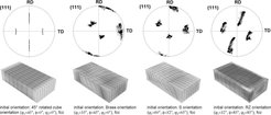
Figure 24: Accumulated misorientations in gray scale coding (light values indicate large misorientations) for aluminum grains together with {111} pole figures after 50 % plane strain deformation for different orientations. The simulations used 12 slip systems. The open squares in the pole figures show the initial orientation (which was the same at all integration points) and the black dots show the orientations after the deformation.

Figure 25: Orientation stability of cube orientation after 50 % plane strain compression for different internal and external boundary conditions predicted by CPFE simulations. Left: Starting condition: Exact cube orientation without initial orientation scatter, Coulomb friction coefficient 0.1. Center: Starting condition: Cube orientation with 2.5° initial orientation scatter, Coulomb friction coefficient 0.1. Right: Starting condition: Cube orientation with 2.5° initial orientation scatter, Coulomb friction coefficient 0.3.
9.2.2. Texture and dislocation density evolution in a bent single-crystalline Copper-nanowire
This section presents an investigation of a bending test using experiments and CPFE simulations. A 23 µm long single crystalline Copper nanowire was produced by focused ion beam fabrication (FIB) [176]. The average crosssection of the specimen was 750 × 750 nm2 . The nanowire was bent in-situ using a micro-manipulator. Characterization was done using scanning electron microscopy (SEM) and electron backscatter diffraction (EBSD). The experiment was compared to simulations conducted by a CPFE analysis using a dislocation density-based constitutive hardening law [23, 24, 174]. The simulations were required for studying the influence of the boundary conditions on the results since they can have substantial influence on the evolution of the texture during bending. The simulations and the experimental results reveal good agreement in terms of texture evolution and elastic spring-back as long as the boundary conditions were reflected accurately. The model provides information about the microstructure evolution in terms of particular material parameters such as the evolution of the dislocation density, figure 26. Similar CPFE simulations on the deformation of pillars by micro-scale compression tests were presented by Raabe et al. [172]. The motivation for selecting this example is to document the capability of the CPFE approach to yield good texture predictions even at small scales where the constitutive law, that is built on a statistical dislocation model [23, 24, 404], reaches its limits due to the small size of the elements.
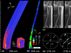
Figure 26: a) Predicted density of the geometrically necessary dislocations during nanowire bending in units of µm−2. b) Experimentally determined geometrically necessary dislocation density, quantified in terms of the average local orientation gradient determined via high resolution EBSD. c) Subsequent scenes taken during bending. d) Pole figures of the bent nanowire obtained from experiment and simulation. The predictions were used to determine the exact boundary conditions that occurred during testing. The crosses indicate the initial orientation. CD: Cross Direction; IBD: Inverse Bending Direction. Bending took place in negative Y-direction.
9.2.3. Texture and microstructure underneath a nanoindent in a Copper single crystal
![Figure 27: Comparison between crystal rotation about the direction [112¯] in the sample reference system underneath the indent at different sections between experiment and simulation (positive values mean counter clockwise rotation) [171, 174, 177].](/3749170/original-1518446875.jpg?t=eyJ3aWR0aCI6MjQ2LCJvYmpfaWQiOjM3NDkxNzB9--b7a77bd4a1b321863677880c10a4b9310f703a13)
Figure 27: Comparison between crystal rotation about the direction [112¯] in the sample reference system underneath the indent at different sections between experiment and simulation (positive values mean counter clockwise rotation) [171, 174, 177].
This example is about the origin of deformation-induced orientation patterns below nanoindents in a {111}-oriented Copper single crystal. The experiments and the simulations were conducted using a conical indenter with spherical tip [170, 171]. The patterns were characterized by neighboring crystalline zones with opposite rotations rates. The approach to analyze and understand the phenomenon was as follows: First, the deformation-induced orientation patterns were investigated in 3D using a high resolution tomographic EBSD technique [174, 177]. This method works by a fully automated alternating serial sectioning and EBSD mapping procedure in a SEM-FIB set-up (3D EBSD) [395, 216, 396]. Second, the problem was modeled using a CPFE method which is based on a constitutive model that uses dislocation densities as state variables [405, 23]. It was found that the rotation pattern induced during indentation were well predicted by the CPFE model. The change of the crystal rotation directions could be explained by the different slip system combinations that were activated due to the geometry of the indenter causing a gradual change in the loading axis that evolved differently at different locations during indentation, figure 27.
9.2.4. Application of a non-local dislocation model including geometrically necessary dislocations to shear tests of aluminum single crystals
The non-local dislocation-based CPFE constitutive model presented in section 4.3 was implemented in the commercial FE code MSC.Marc200x using the subroutine HYPELA2 [388]. The model includes geometrically necessary dislocations (GNDs). The predictions of this non-local model were compared to simple shear experiments on commercially pure aluminum single crystals and to conventional viscoplastic CPFE simulations, figure 28 [98, 406, 24].
In the experiments the maximum equivalent deformation is always observed in the lower left corner of the single crystal and extends diagonally across the crystal. While this behavior is correctly reproduced by the nonlocal model, the phenomenological viscoplastic model predicts the highest strains in the upper left corner of the specimen. One can assume that the better prediction yielded by the non-local model is mainly a consequence of the physically based latent hardening law and the introduction of the GNDs. This assumption is supported by the data presented in figure 30 b) which reveal that substantial densities of GNDs are generated close to the sample borders. For better comparison of the relative contributions of the two types of dislocations, figures 30 b) and c) show both, the distributions of the GNDs and the densities of statistically stored dislocations on the crystal surface.
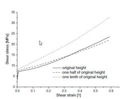
Figure 29: Simulated shear stress strain curves for samples with different height-to-length ratios demonstrating the size sensitivity of the non-local dislocation model.
Another advantage of the use of GNDs in a CPFE constitutive law is that the model is rendered length scale dependent. Therefore, the shear simulation presented above was repeated for a set of three cases which were characterized by different height-to-length ratios. For this purpose the height H of the sheared sample was changed to one half and one tenth of the original height H0, respectively. The resulting shear stress–shear strain curves are shown in figure 29. Equations (26), (27), (38), and (39) reveal that the GND density contributes to the passing stress and to the multiplication term of the immobile dislocation. For this reason one would expect higher predicted stresses for the thinnest sample owing to the relative increase of zones which are mechanically affected by the presence of interfaces. This is indeed confirmed by figure 29. Figures 30 b), e), h) show how the relative size of the zone that is influenced by the GNDs increases with decreasing sample height. This increased GND density leads also to an increase in the statistically stored dislocation density as expected and shown in figures 30 c), f), i). Additionally figures 30 a), d), g) reveal that the predicted texture evolution of the crystal is affected by the non-local model. This results in an intersection of the stress–strain curves for H = H0 and H = H0/2 in figure 29. The strong influence of incorporating GNDs into the CPFE framework on the predicted reorientation rates is due to the penalty effect they impose. This means that each reorientation step which introduces an orientation divergence with respect to the neighborhood [117] is impeded owing to the corresponding introduction of additional GNDs.
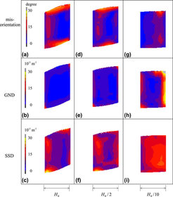
Figure 30: Comparisons of dislocation densities and misorientation for different samples after a 30 % shear deformation. Heights of samples are H = H0, H = H0/2 and H = H0/10 (all plots are scaled to the same heigth for a better comparison), respectively. GND: geometrically necessary dislocation density, SSD: statistically stored dislocation density.
Another advantage of the use of GNDs in a CPFE constitutive law is that the model is rendered length scale dependent. Therefore, the shear simulation presented above was repeated for a set of three cases which were characterized by different height-to-length ratios. For this purpose the height H of the sheared sample was changed to one half and one tenth of the original height H0, respectively. The resulting shear stress–shear strain curves are shown in figure 29. Equations (26), (27), (38), and (39) reveal that the GND density contributes to the passing stress and to the multiplication term of the immobile dislocation. For this reason one would expect higher predicted stresses for the thinnest sample owing to the relative increase of zones which are mechanically affected by the presence of interfaces. This is indeed confirmed by figure 29. Figures 30 b), e), h) show how the relative size of the zone that is influenced by the GNDs increases with decreasing sample height. This increased GND density leads also to an increase in the statistically stored dislocation density as expected and shown in figures 30 c), f), i). Additionally figures 30 a), d), g) reveal that the predicted texture evolution of the crystal is affected by the non-local model. This results in an intersection of the stress–strain curves for H = H0 and H = H0/2 in figure 29. The strong influence of incorporating GNDs into the CPFE framework on the predicted reorientation rates is due to the penalty effect they impose. This means that each reorientation step which introduces an orientation divergence with respect to the neighborhood [117] is impeded owing to the corresponding introduction of additional GNDs.
9.2.5. Evolution of crystallographic dislocation density in a crystal plasticity modeling framework
![Figure 31: CPFE simulated and experimentally observed orientation-dependence of the stress-strain profile of aluminum single crystals during tensile loading [19].](/3749214/original-1518446876.jpg?t=eyJ3aWR0aCI6MjQ2LCJvYmpfaWQiOjM3NDkyMTR9--ab99a884dbd0b15ce0c2d289d2078e7137e7e533)
Figure 31: CPFE simulated and experimentally observed orientation-dependence of the stress-strain profile of aluminum single crystals during tensile loading [19].
Arsenlis and Parks implemented dislocation-based constitutive laws into a CPFE simulation framework [19]. The basics and further developments along these lines were published in a sequence of works where the recent emphasis is placed on extracting constitutive information for instance on strain hardening form discrete dislocation modeling [19, 18, 65, 9]. They suggested a constitutive formulation where dislocation density variables gradually evolve from initial conditions according to a set of structure evolution formulations considering basic dislocation mechanics such as the continuity of dislocation line and Burgers vector conservation in a set of generic multiplication and annihilation processes [19]. The density evolution equations use three classes of internal variables, namely, the average dislocation mobility, the average segment length, and the capture radii. The model used a set of 18 discrete dislocation densities comprising 12 edge and 6 screw components.
The model was implemented in a CPFE framework to study the polyslip behavior of aluminum single crystals of different initial crystallographic orientation under tensile loading, figure 31. The results do not only yield reasonable mechanical stress-strain response for the differently oriented crystals, but also provided insight about the development of the dislocation structure responsible for the respective plastic behavior observed. A similar approach where conventional viscoplastic hardening rules were replaced by dislocation density evolution laws including also geometrically necessary dislcoations was suggested by Ma et al. [23, 24, 25, 404].
9.2.6. Application of a grain boundary constitutive model in CPFE bicrystal
This example used a dislocation-based constitutive model to incorporate the mechanical interaction between mobile dislocations and grain boundaries into the CPFE framework. The approach is based on the introduction of an additional activation energy into the rate equation for mobile dislocations in the vicinity of grain boundaries. The energy barrier is derived by using an elastic model for thermally activated dislocation penetration events through grain boundaries. The model was presented in detail in section 4.3.3 and in [24, 25]. The approach is applied to the case of 50 % (frictionless) simple shear deformation of three aluminum bicrystals with a small, intermediate, and high angle grain boundary, respectively, parallel to the shear plane. The simulations are compared to experiments with respect to equivalent surface strain and texture. The constitutive parameters were tted by using the stress{strain response of a single crystal simple shear test illustrated in Figures 28 and 29.
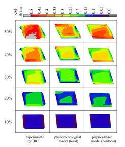
Figures 32 - 34 show the comparison of the von Mises strain patterns obtained from the experiment (left column), from the simulation with a viscoplastic law (no interface model; center column), and from the dislocationbased CPFE simulation including GNDs and a geometrical model for the grain boundary resistance as introduced in section 4.3.3 (right column). The gures show the von Mises strain distributions for ve stages of shear with a constant increase of 10 % per load step. The experiments reveal in all cases the strong constraint imposed by the grain boundary. Even for the small angle grain boundary (7.4°) the experiment indicates strain separation among the two crystals. With increasing grain boundary misorientation the heterogeneous distribution of the strain between the grains becomes more pronounced. The corresponding viscoplastic CPFE simulation (local law, central column of gures 32 - 34) does not adequately reproduce the in uence of the grain boundaries on the strain distribution. This applies in particular for the two bicrystals which have a small and intermediate angle grain boundary, respectively. For the bicrystal with the high angle grain boundary, gure 34, the empirical (local) model is capable of predicting some, although not all, characteristics of the strain separation between the two crystals. The partial success of the simulation with the empirical viscoplastic hardening law in case of the high angle grain boundary is attributed to the strong e ect of the change in the Schmid factor across the interface, i.e. kinematic effects prevail over dislocation density e ects in this case.
Bate [155] conducted a similar CPFE simulation of bicrystal deformation. He observed not only orientation splitting and strain separation among the abutting grains but also severe deformation banding in both crystals at an olique angle to the grain boundary. This work demonstrates very nicely the far reaching e ect of a grain boundary causing substantial deformation heterogeneity in the grain interior.
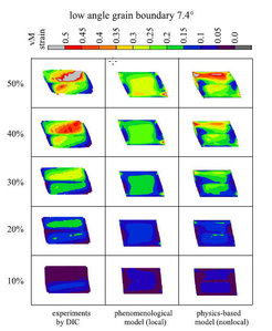
Figure 32: Simple shear test of a bicrystal with a 7.4° low angle grain boundary (3.1 mm long, 2.0 mm thick and 2.2 mm high). Comparison of the von Mises strain patterns as obtained from the experiment via digital image correlation (DIC, left column), from the simulation with a conventional viscoplastic constitutive law (central column), and from the simulation which uses an advanced dislocation-based non-local model (see section 4.3) (right column).
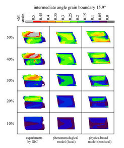
Figure 33: Simple shear test of a bicrystal with a 15.9° intermediate angle grain boundary (3.1 mm long, 2.0 mm thick and 2.2 mm high). Comparison of the von Mises strain patterns as obtained from the experiment via digital image correlation (DIC, left column), from the simulation with a conventional viscoplastic constitutive law (central column), and from the simulation which uses an advanced dislocation-based non-local model (see section 4.3) (right column).
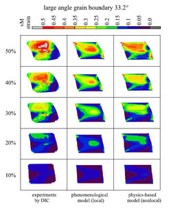
Figure 34: Simple shear test of a bicrystal with a 33.2° high angle grain boundary (3.1 mm long, 2.0 mm thick and 2.2 mm high). Comparison of the von Mises strain patterns as obtained from the experiment via digital image correlation (DIC, left column), from the simulation with a conventional viscoplastic constitutive law (central column), and from the simulation which uses an advanced dislocation-based non-local model (see section 4.3) (right column).
9.2.7. Modeling of the grain size dependence of polycrystal mechanics
The group of Evers, Brekelmans, and Geers investigated the way size dependent effects are associated with interfaces and geometrically necessary dislocations in CPFE and Taylor-type homogenization frameworks [20, 21, 26, 83]. For instance in [20], a local plastic strain gradient dependent crystal plasticity model was suggested which is capable of describing the grain size dependent mechanical response of polycrystals.
This approach consists of assigning geometrically necessary dislocation (GND) populations to intragranular incompatible deformations that arise as a result of the existence of grain boundaries between abutting crystals. The polycrystal appears in this model as a statistical set of bicrystal aggregates which altogether provide an orientation-dependent density of misfit dislcoations which in turn provide extra hardening to the system. As the intragranular heterogeneous deformation is related to the grain size, the amount of GND-enhanced hardening grows as the crystal size drops, figure 35.
The conventional slip system hardening through statistically stored dislocations is described by a system of phenomenological equations that capture the influence of self and latent hardening. The model provides a crystallographically and physically motivated hardening dependence in polycrystals based on their grain size. The morphological texture can be incorporated through the inclination and crystallographic distribution of the grain boundaries and their mutual weights.
![Figure 35: Stress-strain curves for average grain diameters of 14, 33 and 220 µm, represented by the upper, middle and lower slide line curves (of each type), respectively. The dashed lines indicate results from earlier finite element calculations of Arsenlis and Parks (2000) and the bullets are experimental results from Hansen (1979). (a) Results using the assumption of SSD and GND strength addition. (b) Results using the assumption of SSD and GND density addition [20], showing a closer agreement with experimental data.](/3749269/original-1518446876.jpg?t=eyJ3aWR0aCI6MjQ2LCJvYmpfaWQiOjM3NDkyNjl9--f95e2f3a1af114c3f0cd9bc5b7a5803b4b10a99a)
9.2.8. Three-dimensional aspects of oligocrystal plasticity
Zhao et al. [32] conducted a study of plastic strain localization and deformation-induced surface roughening in an aluminum polycrystal consiting of a small set of coarse grains (oligocrystal). A dogbone specimen is plastically deformed under uniaxial tensile loading. During deformation, the history of strain localization, surface roughening, microstructure and in-grain fragmentation is recorded. Using a CPFE model, corresponding one-to-one high resolution simulations are conducted, figure 36. The study reveals that the grain topology and microtexture have a significant influence on the origin of strain heterogeneity. Moreover, it suggests that the final surface roughening profiles are related both to the macro strain localization and to the intra-grain interaction. Finally slip lines observed on the surface of the samples are used to probe the activation of slip systems in detail.
![Figure 36: Study by Zhao et al. on plastic strain localization and deformation-induced surface roughening in a 3D aluminum polycrystal consisting of a small assembly of coarse grains (oligocrystal) [32].](/3749280/original-1518446877.jpg?t=eyJ3aWR0aCI6MjQ2LCJvYmpfaWQiOjM3NDkyODB9--e42e5c7dcf4ca6c36ee6ce9ed46c4169f2e2e072)
Figure 36: Study by Zhao et al. on plastic strain localization and deformation-induced surface roughening in a 3D aluminum polycrystal consisting of a small assembly of coarse grains (oligocrystal) [32].
![Figure 37: Simulation of Beaudoin et al. of a grain cluster consisting originally of Soriented crystals (fcc). Results are shown after a thickness reduction of 85 % a) section with stable S orientations; b) section with cube bands. Images are scaled by a factor of ten in thickness (N) direction [110].](/3749258/original-1518446876.jpg?t=eyJ3aWR0aCI6MjQ2LCJvYmpfaWQiOjM3NDkyNTh9--cbd94490e4e32d1fac817794dcf021490340053a)
Figure 37: Simulation of Beaudoin et al. of a grain cluster consisting originally of Soriented crystals (fcc). Results are shown after a thickness reduction of 85 % a) section with stable S orientations; b) section with cube bands. Images are scaled by a factor of ten in thickness (N) direction [110].
Particular attention in the analysis is placed on the ability of the CPFE model to capture the fine details of the surface roughening effects, orientationdependent strain localization, and the pattern of activation of slip systems in the grains. It was observed that the grain stretching over the whole width of the dogbone specimen was remarkably soft. The absence of dislocation barriers provided by grain boundaries promotes strain localization owing to a single isolated soft grain. Due to the significant thickness reduction, a severe surface roughening is particularly observed in the soft region of the sample.
Similar studies on the mechanical heterogeneity and the texture evolution in coarse grained samples were presented by [110] and [14]. Common to these works is that they show, depending on grain orientation, substantial in-grain orientation fragmentation and strain localization.
Beaudoin et al. [110] idealize in their study a simple polycrystal as a three-dimensional arrangements of 8 grains, each consisting of many elements per crystal. Non-uniform deformations within individual grains lead to the development of domains that are separated by boundaries of high misorientation. Also, localized shearing is seen to occur at the microscopic grain scale. The authors also discuss the importance of such plastic and orientation localization phenomena for recrystallization nucleation (see also next section). Particularly the landmark paper of Beaudoin et al. [110] motivated further investigations on in-grain orientation scatter (grain fragementation) and corresponding approaches to classify grains according to their kinematic stability upon loading. The aim of these works was to systematically learn which types of grains (texture components) tend to build up large orientation gradients under certain loading states [92, 117], figure 37.
9.2.9. Simulation of recrystallization using CPFE micromechanical results
In this section we present approaches for predicting primary static recrystallization and related grain coarsening phenomena by combining CPFE simulations with Monte Carlo, cellular automaton, or network models [155, 156, 159, 148, 162, 163, 407]. Such combined methods can predict microstructures and texture evolution during thermomechanical treatment. The advantage of the approach is that they consider the material heterogeneity of the deformation microstructure and recrystallization phenomena as opposed to classical statistical approaches which are based on the assumption of material homogeneity.
Bate [155] assumed that the von Mises stress obtained from a CPFE bicrystal model is linearly related to the substructure density in deformed metals that undergo extensive dynamic recovery. From the CPFE results he constructed a cell structure and used it as input to a two-dimensional network model for recrystallization simulation. Cell centres are included at random coordinates, with specific exclusion rules to ensure that the cell size is inversely proportional to the local von Mises stress. Cell orientations are interpolated from the CPFE results and the initial network is set up via Dirichlet tessellation. Figure 38 reveals two stages in the simulation. At an early phase of annealing, the essential features of the deformed structure remain apparent. The crystallite size is larger, and more high angle grain boundaries emerge, near the original grain boundary. There are some high angle boundaries associated with the deformation inhomogeneity in the upper grain. At the later stage, considerable strain-induced boundary migration has occurred. Some of the new grains have orientations corresponding to a cube texture rotated by 15° about the extension direction (circled points in Figure 38).
![Figure 38: Results of Bate from a network annealing model with the initial representation of microstructure derived from a CPFE simulation [155]. The initial number of crystallites was 900. Only grain boundaries with misorientations greater than 3° are shown. Darker grains are near the cube orientation. The configuration at 400 remaining crystallites is shown in (b). The resulting grain orientations are given in the {001} pole figure [155].](/3749291/original-1518446877.jpg?t=eyJ3aWR0aCI6MjQ2LCJvYmpfaWQiOjM3NDkyOTF9--9a187e1edca216ea1ec82e6199bd0b73a65b501d)
Figure 38: Results of Bate from a network annealing model with the initial representation of microstructure derived from a CPFE simulation [155]. The initial number of crystallites was 900. Only grain boundaries with misorientations greater than 3° are shown. Darker grains are near the cube orientation. The configuration at 400 remaining crystallites is shown in (b). The resulting grain orientations are given in the {001} pole figure [155].
Raabe and Becker used a method where the results of a CPFE simulation serve as a starting microstructure for a subsequent discrete cellular automaton recrystallization simulation. The CPFE model simulated plane strain compression of aluminum with a columnar coarse grain structure to a total logarithmic strain of 0.434 [156, 408]. The values of the state variables (dislocation density, crystal orientation) given at the integration points of the FE mesh were mapped on the cellular automaton lattice. The original size of the specimen which provided the input microstructure to the CPFE simulation gave a lattice point spacing of 61.9 µm. The maximum driving force in the region arising from the stored dislocation density was about 1 MPa. The annealing temperature was 800 K. High angle grain boundaries were characterized by an activation energy for the mobility of 1.3 eV. Small angle grain boundaries were assumed to be immobile.
The nucleation process during primary static recrystallization has been explained for pure aluminum in terms of discontinuous subgrain growth. According to this model nucleation takes place in areas which reveal high misorientations among neighboring subgrains and a high local driving force for curvature driven discontinuous subgrain coarsening. The present simulation approach works above the subgrain scale, i.e. it does not explicitly describe cell walls and subgrain coarsening phenomena such as the approach of Bate [155]. Instead, it incorporates nucleation on a more phenomenological basis using the kinetic and thermodynamic instability criteria known from classical recrystallization theory. Kinetic instability means that nucleation leads to the formation of a mobile high angle grain boundary which can sweep the deformed matrix. Thermodynamic instability means that the stored energy changes across the new high angle grain boundary gives a net driving force. Nucleation in this simulation is performed in accord with these two criteria [408], figure 39. A similar approach of applying a cellular automaton model to CPFE simulation data of a deformed superalloy for the prediction of local recrystallization phenomena was used by [162], figure 40.

Figure 39: 2D simulation of recrystallization in deformed aluminum on the basis of CPFE data. Dislocation density in terms of the driving force (top) and microtexture (bottom) at an intermediate recrystallization step for different nucleation conditions. The texture is given in terms of the magnitude of the Rodriguez vector. The gray regions indicate recrystallization. The maximum occurring driving force is 1 MPa. The thick white lines indicate grain boundaries above 15°. The thin green lines indicate misorientations between 5° and 15° . The simulation parameters are: 800 K; thermodynamic instability criterion: site-saturated spontaneous nucleation in cells with at least 50 % (a), 60 % (b), and 70 % (c), respectively, of the maximum occurring dislocation density (threshold value).
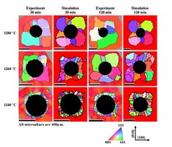
Figure 40: Simulation results, showing evolving recrystallization microstructures around an indent in a Ni-base superalloy, compared to EBSD measurements. The normal Miller indices are indicted in terms of an inverse pole figure color scheme. The arrows indicate the orientation of the parent single crystal. White lines in the experimental results indicate first order annealing twins, black lines are used for high angle grain boundaries with a misorientation of more than 15°.

9.2.10. Simulations of multiphase TRIP steels hier geht’s weiter mit den Bildern
The mechanical behavior of a TRIP-assisted steel is simulated for an uniaxially loaded sample composed of a single austenitic grain surrounded by a matrix of ferritic grains. The purpose of the present simulation is to study the TRIP effect as a function of crystallographic orientations, i.e., the orientation of the austenitic and ferritic grains with respect to the applied load as well as the orientation mismatch between neighboring grains.
In the present analysis, a cubic sample of size a3 (see figure 41) that represents a single grain of austenite surrounded by a matrix of ferrite is considered. In the undeformed state, the polyhedral austenitic grain occupies approximately 13 % of the total volume of the sample. The sample is initially stress-free and is subsequently subjected to a uniaxial tensile loading, which is prescribed through the following boundary conditions: (i) The normal displacement and the tangential traction on the external faces 2, 3 and 5 are set to zero. (ii) The normal displacement on the external face 1 equals to u1 = 10-4 at, with time interval 0 < t ≤ 2000 s, and the tangential traction is set to zero. (iii) The remaining faces (4 and 6) are traction-free. The applied boundary conditions correspond to an axial straining rate of 10-4 s-1 . The simulation is performed at a constant temperature of 300 K. The parameters used in the model for the ferrite are the same as those used in [82], which are representative of a ferrite-based matrix in typical multiphase TRIP steels. The model parameters for the austenite are the same as those used in [82], which are calibrated from a TRIP steel with an austenite carbon concentration of 1.4 wt %. In the simulations, four TRIP steel microstructures with different austenitic and ferritic crystallographic orientations (textures) are considered, namely (1) [100]A-[100]F, (2) [100]A-[111]F, (3) [111]A-[100]F and (4) [111]A-[111]F-loaded samples.
Figure 42 a and b illustrate the effective stress–strain response and the evolution of the austenitic volume fraction of the TRIP steel samples 1–4. In general, samples 2 and 4 (with [111]F-loaded ferritic matrix) show a higher axial stress response than samples 1 and 3 (with [100]F-loaded ferritic matrix), which indicates that ferrite loaded in [111]F direction is stronger than that loaded in [100]F direction (an analysis of the Schmid stress suggests that [111]F-loaded ferrite gives the highest stress response under uniaxial tensile loading). Furthermore, samples containing a [111]A-loaded austenitic grain give a relatively high initial yield stress in comparison to the corresponding samples with a [100]A-loaded austenitic grain. As reported in [263, 78, 82], [100]A-loaded austenite is a more favorable orientation for transformation. In other words, [100]A-loaded austenite transforms at a low stress level, whereas transformation of the [111]A-loaded austenite occurs at a relatively high stress level. This is in agreement with experimental observations for TRIP steels (see, e.g., [409, 410]). In addition, the [100]A-loaded austenitic grain (in samples 1 and 2) transforms at a higher rate than the austenitic grain loaded in [111]A direction (samples 3 and 4), as depicted in figure 42 b. At about 0.08 axial strain, the austenitic grain in samples 1 and 2 has been (almost) fully transformed into the harder martensitic phase. Consequently, the axial stress response of samples 1 and 2 increases rapidly after about 0.08 axial strain. Furthermore, figure 42 b shows that transformation behavior in the austenitic grain is dependent not only on the orientation of the austenitic grain itself but also on the orientation of the surrounding ferritic matrix. The effect of the mismatch between the orientation of the transforming austenitic grain and the surrounding matrix can be quite significant (compare, e.g., samples 3 and 4).

Figure 42: Axial stress response (a) and the evolution of austenitic volume fraction (b) as a function of the axial logarithmic strain of TRIP steel samples consisting of an austenitic grain embedded in a ferritic matrix.
9.2.11. Evaluating CPFE results for damage prediction
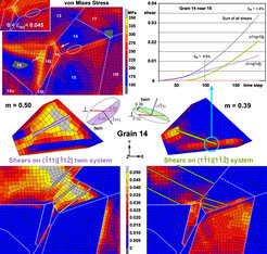
At present, the fracture initiation parameter (fip) introduced in section 7 is a static metric; an evolving fip has not yet been developed. However, it is clear that CPFE modeling provides the information necessary to evaluate an evolving fip. Preliminary CPFE modeling (using phenomenological hardening relationships) of one of the microstructures used to develop the fip showed greatly enhanced activation of the secondary twining system responsible for the observed microcrack where it occurred (see figures 43 and 44). Only spatially resolved crystal plasticity could predict such a result. Remarkably, elements surrounding this boundary had only a modest stress– strain history (i.e. modest strain energy). The twinning system responsible for the crack appeared to geometrically accommodate a strain concentration that occurred on the other (upper left) side of grain 14. Thus, damage developed in response to a nearby local strain concentration at the left edge of grain 14, where strain transfer across a grain boundary some distance from the strain concentration led to weakening of the boundary. This example suggests that while large local strains may be the ultimate driving force for damage, the damage may not be nucleated where the large strains occur.
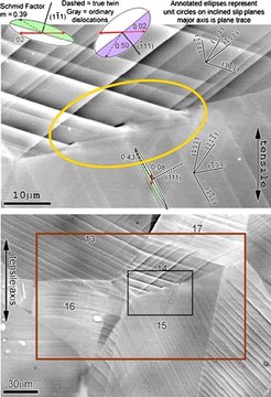
Figure 43: Microcracks arising from twin interactions with a grain boundary in TiAl. Ellipses represent tilted unit circles on slip planes identi ed by poles, with slip or twinning vectors as indicated, with shaded half below the surface. Schmid factors are based upon the global (vertical) stress direction. The surrounding microstructure was modeled using CPFE.
9.3. Macroscopic examples
9.3.1. Using elastic constants from ab initio simulations for predicting textures and texture-dependent elastic properties of β-Titanium
This section presents applications on the prediction of textures and texturedependent elastic properties using multi-scale CPFE simulations where the elastic constants are obtained by ab initio simulations (density-functional theory) [411]. We apply this approach to Ti-Nb binary biomaterial alloys that can be used for human implants. The two models we combine (ab initio, CPFE) work at very different length and time scales. The strength of this combination for predicting certain polycrystal properties lies in the fact that continuum-based theoretical models such as CPFE rely on a number of ground state properties (e.g. elastic tensor). The use of texture data is in such cases (elasticity) suficient to predict realistic data also for complex polycrystalline aggregates irrespective of their thermo-mechanical process history. A particular advantage of using an FEM based methods rather than an analytical or semi-analytical approach for obtaining the polycrystal stiffness from corresponding ab initio single crystal data is that it allows one to consider any kind of crystallographic texture including also intra-or in-grain interactions. Most homogenization methods for obtaining the elastic modulus of a polycrystal such as the Voigt, Reuss, Hill, or Hershey [302, 301, 412, 413] models usually either neglect texture or assume highly simplified boundary conditions. A further important aspect of using ab initio elastic results in conjunction with crystal mechanical simulations is the fact that for the elastic constants of single crystals (which are a necessary input to CPFE simulations) experimental data are often lacking [414, 415]. Details about the ab initio calculations used in this section are given in [416].
The goal of the first example is to investigate the dependence of the rolling texture evolution of two β-Ti-Nb binary alloys on the elastic properties. For this purpose we used different elastic constants in terms of the magnitude of the tensor components and the elastic anisotropy. These elastic constants which were obtained from ab initio electronic structure calculations [416] served as constitutive input variables in a CPFE simulation in conjunction with a viscoplastic hardening law [415].
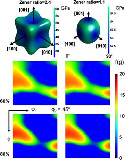
β-Ti alloys have bcc crystal lattice structure. At room temperature the structure can be stabilized by the addition of Nb or Mo. As slip systems we used {110}, {112}, and {123} slip planes and (111)/2 Burgers vectors [417, 418]. Two alloys were investigated, namely, Ti-18 at.%Nb and Ti-31 at.%Nb. The elastic constants for Ti-18 at.%Nb as calculated by the ab initio method were C11 = 49.8 GPa, C12 = 21.4 GPa, and C44 = 33.1 GPa. The Zener anisotropy ratio which is defined as 2C44/(C11 − C12) amounts to 2.4. The predicted elastic constants for Ti-31 at.%Nb were C11 = 72.6 GPa, C12 = 31.1 GPa, and C44 = 19.3 GPa giving a Zener ratio of 1.1. The rolling texture simulation was conducted using plane strain compression boundary conditions and random initial texture. Figure 45 shows the predicted crystallographic textures in terms of a set of ϕ2 = 45° sections through Euler space for the two cases. The results show that there is no pronounced relationship between slip system selection and the magnitude and anisotropy of the elastic constants.
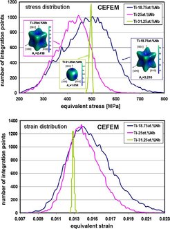
A second (elastic) example of using ab initio elastic stiffness constants in a CPFE framework is shown in figure 46. The two diagrams present the distribution of the equivalent elastic stress and strain values in a randomly textured polycrystalline aggregate consisting of 200 grains and 32 × 32 × 32 elements for three different elastic tensors (magnitude, anisotropy) of three β-Ti alloys. The specimens were subjected to a unidirectional purely elastic tensile load. The data show that an increase in the elastic anisotropy (quantified here in terms of the Zener ratio) leads to a remarkable increase in the spread of the stress-strain distribution. This means that local elastic loads (hot spots) among neighboring grains become more frequent as the elastic anisotropy increases. This effect may play a role in such diverse fields as internal stress evolution and stress corrosion cracking.
![Figure 47: Representation of the FE meshes used by Delannay et al. [126]. (a) Initial mesh in the simulation where brick shapes were used. (b) Result of plane strain compression (periodic boundary conditions, 70 % thickness reduction along x3). (c) Representation of one grain in the simulation as truncated octahedron [126].](/3749390/original-1518446879.jpg?t=eyJ3aWR0aCI6MjQ2LCJvYmpfaWQiOjM3NDkzOTB9--c12c90d0d1a7aaee38ffae6382585f7421367238)
9.3.2. Grain meshing strategies in CPFE modeling
Delannay et al. [126] tested a set of di erent simulation approaches for the prediction of texture development and microscopic strain heterogeneity in cold rolled ultra low carbon and multiphase steels under uniaxial tension, figure 47. The polycrystalline sample is represented by a nite element mesh that is loaded under periodic boundary conditions. The individual crystals are shaped as cubes or as truncated octahedrons, de ning three di erent levels of mesh re nement. Simulations rely on a simplified implementation of crystal plasticity, in which elastic strains are considered in nitesimal. The constitutive law is integrated fully implicitly in a reference frame that is tied to the crystal lattice. The results of the micro-macro modeling are compared to experimental data. The authors observe that the simulations with truncated octahedral grains yield improved predictions compared to those with cuboidal grains. This result is of relevance particularly for engineering applications of CPFE models where economical mesh and texture mapping strategies must be used owing to time and mesh size constraints.
9.3.3. Simulation of earing during cup drawing of steel and aluminum
This section presents examples of the CPFE method in the field of engineering forming problems at the macroscopic scale. The first example is about the prediction of earing during forming of a ferritic 17 %Cr (X6Cr17, AISI 430) stainless steel sheet considering through-thickness gradients of the crystallographic texture. A texture component CPFE method (TCCP-FEM) [142, 119, 13, 128, 130] is used for the simulation of cup drawing. The simulation includes the through-thickness texture gradient of the starting hot band [419, 420]. The simulation predicts the development of the orientation distribution and the earing profile during cup forming considering {110}(111), {112}(111), and {123}(111) slip systems [417]. The results are compared to another FE simulation (based on a Hill48 yield surface [421]) and to experimental data.
Figure 48 shows the predicted and the measured earing profiles in terms of the relative ear height (normalized by the average height). The ear profile predicted by the simulation with the texture components of only the center layer (s =0.0) reveals a shape with a broad maximum around 45°. On the other hand, the profile simulated with the texture of only the sub-surface layer (s =0.8) is characterized by a broad minimum in the same region (45°). The reason for this difference is that the texture components fitted from each respective layer of the material reproduced various initial textures and, consequently, different anisotropy. The course of the ear profile calculated by using only the texture components of the sub-surface layer, s = 0.8, can be presumably explained by the influence of the relatively weak intensity of the {111}(112) component of the starting texture in this layer. The high orientation density of the {111}(112) texture component in the initial texture of the mid-thickness layer (s =0.0) is responsible for the ear shape with the strong peak at 45° observed for the simulation that was performed by using the texture components of this layer. The results also show that the texture component CPFE simulation which used the gradient texture (1/3 of the through-thickness volume occupied by the center layer texture (s =0.0) and 2/3 of the volume occupied by the sub-surface layer texture (s =0.8) where 1/3 accounts for the bottom and 1/3 for the top surface region, respectively) fits the experimental data better than that obtained from the Hill48 yield surface prediction. The second example, figure 49, shows a similar comparison between experiment and simulation for a cube-textured aluminum sheet after cup drawing. In this case no through-thickness texture gradients existed.
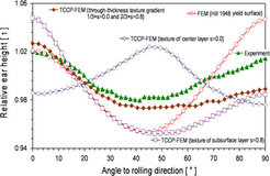
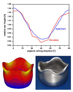
Figure 49: Comparison of the earing profile between experiment and texture component CPFE simulation for a cube-textured aluminum sheet after cup drawing.
9.3.4. Virtual material testing for stamping simulations based on crystal plasticity simulations
In the modern practice of simulating complex industrial stamping operations, the prediction of springback still lacks accuracy. In current commercial software packages used for instance in the automotive industry, various empirical constitutive laws for stamping are available. As these approaches provide only limited empirical access to the material anisotropy they do not properly take into account the effects of microstructure and texture and their evolution during deformation. The CPFE method bridges the gap between the polycrystalline texture and macroscopic mechanical properties and opens the path to a more profound consideration of metal anisotropy in stamping process simulations.
The example in this section presents an application of the CPFE method for the concept of virtual material testing using a representative volume element (RVE) approach [217]. By using such numerical test protocols it becomes possible to determine the actual shape of the yield locus as well as corresponding Lankford parameters through CPFE simulations, and to use this information to calibrate empirical constitutive models used for example in the automotive industry. Along with standard uniaxial tensile tests, other strain paths can be numerically monitored such as biaxial tensile, compressive or shear tests. In the present example the use of the CPFE method for virtual testing is demonstrated for a low carbon steel grade. The parameters of an empirical yield surface function were calibrated using CPFE predictions and a commercial stamping part was simulated, figure 50.
![Figure 50: Application of the CPFE method for virtual material testing using a representative volume element (RVE) approach. The parameters of anempirical yield locus function were calibrated for a low-carbon steel grade using CPFE and a commercial stamping part was simulated [217].](/3749423/original-1518446880.jpg?t=eyJ3aWR0aCI6MjQ2LCJvYmpfaWQiOjM3NDk0MjN9--a72cdc080d6da0a491f5dfb1a77e5d0ab83f3f47)
Figure 50: Application of the CPFE method for virtual material testing using a representative volume element (RVE) approach. The parameters of anempirical yield locus function were calibrated for a low-carbon steel grade using CPFE and a commercial stamping part was simulated [217].


![Figure 27: Comparison between crystal rotation about the direction [112¯] in the sample reference system underneath the indent at different sections between experiment and simulation (positive values mean counter clockwise rotation) [171, 174, 177]. Figure 27: Comparison between crystal rotation about the direction [112¯] in the sample reference system underneath the indent at different sections between experiment and simulation (positive values mean counter clockwise rotation) [171, 174, 177].](/3749170/original-1518446875.jpg?t=eyJ3aWR0aCI6MzQxLCJmaWxlX2V4dGVuc2lvbiI6ImpwZyIsIm9ial9pZCI6Mzc0OTE3MH0%3D--4f780cbec8856899114330a5d489dace9a9d05c7)


![Figure 31: CPFE simulated and experimentally observed orientation-dependence of the stress-strain profile of aluminum single crystals during tensile loading [19]. Figure 31: CPFE simulated and experimentally observed orientation-dependence of the stress-strain profile of aluminum single crystals during tensile loading [19].](/3749214/original-1518446876.jpg?t=eyJ3aWR0aCI6MzQxLCJmaWxlX2V4dGVuc2lvbiI6ImpwZyIsIm9ial9pZCI6Mzc0OTIxNH0%3D--600d15c05e7fafd549c187314bb3521b996ca40b)


![Figure 35: Stress-strain curves for average grain diameters of 14, 33 and 220 µm, represented by the upper, middle and lower slide line curves (of each type), respectively. The dashed lines indicate results from earlier finite element calculations of Arsenlis and Parks (2000) and the bullets are experimental results from Hansen (1979). (a) Results using the assumption of SSD and GND strength addition. (b) Results using the assumption of SSD and GND density addition [20], showing a closer agreement with experimental data. Figure 35: Stress-strain curves for average grain diameters of 14, 33 and 220 µm, represented by the upper, middle and lower slide line curves (of each type), respectively. The dashed lines indicate results from earlier finite element calculations of Arsenlis and Parks (2000) and the bullets are experimental results from Hansen (1979). (a) Results using the assumption of SSD and GND strength addition. (b) Results using the assumption of SSD and GND density addition [20], showing a closer agreement with experimental data.](/3749269/original-1518446876.jpg?t=eyJ3aWR0aCI6ODQ4LCJmaWxlX2V4dGVuc2lvbiI6ImpwZyIsIm9ial9pZCI6Mzc0OTI2OX0%3D--d6c7fb61cc85cf44d8df356f27ce5c12df293a25)
![Figure 36: Study by Zhao et al. on plastic strain localization and deformation-induced surface roughening in a 3D aluminum polycrystal consisting of a small assembly of coarse grains (oligocrystal) [32]. Figure 36: Study by Zhao et al. on plastic strain localization and deformation-induced surface roughening in a 3D aluminum polycrystal consisting of a small assembly of coarse grains (oligocrystal) [32].](/3749280/original-1518446877.jpg?t=eyJ3aWR0aCI6ODQ4LCJmaWxlX2V4dGVuc2lvbiI6ImpwZyIsIm9ial9pZCI6Mzc0OTI4MH0%3D--3d649492232ed10ee9236ea0e72c446b5bbf8b6d)
![Figure 37: Simulation of Beaudoin et al. of a grain cluster consisting originally of Soriented crystals (fcc). Results are shown after a thickness reduction of 85 % a) section with stable S orientations; b) section with cube bands. Images are scaled by a factor of ten in thickness (N) direction [110]. Figure 37: Simulation of Beaudoin et al. of a grain cluster consisting originally of Soriented crystals (fcc). Results are shown after a thickness reduction of 85 % a) section with stable S orientations; b) section with cube bands. Images are scaled by a factor of ten in thickness (N) direction [110].](/3749258/original-1518446876.jpg?t=eyJ3aWR0aCI6MzQxLCJmaWxlX2V4dGVuc2lvbiI6ImpwZyIsIm9ial9pZCI6Mzc0OTI1OH0%3D--aaac3b2e8b570395bc4522ba02905e5d17bc0de3)
![Figure 38: Results of Bate from a network annealing model with the initial representation of microstructure derived from a CPFE simulation [155]. The initial number of crystallites was 900. Only grain boundaries with misorientations greater than 3° are shown. Darker grains are near the cube orientation. The configuration at 400 remaining crystallites is shown in (b). The resulting grain orientations are given in the {001} pole figure [155]. Figure 38: Results of Bate from a network annealing model with the initial representation of microstructure derived from a CPFE simulation [155]. The initial number of crystallites was 900. Only grain boundaries with misorientations greater than 3° are shown. Darker grains are near the cube orientation. The configuration at 400 remaining crystallites is shown in (b). The resulting grain orientations are given in the {001} pole figure [155].](/3749291/original-1518446877.jpg?t=eyJ3aWR0aCI6ODQ4LCJmaWxlX2V4dGVuc2lvbiI6ImpwZyIsIm9ial9pZCI6Mzc0OTI5MX0%3D--38b96aa31569afc05b5b55ab5ae72adf89d3ebb3)


![Figure 47: Representation of the FE meshes used by Delannay et al. [126]. (a) Initial mesh in the simulation where brick shapes were used. (b) Result of plane strain compression (periodic boundary conditions, 70 % thickness reduction along x3). (c) Representation of one grain in the simulation as truncated octahedron [126]. Figure 47: Representation of the FE meshes used by Delannay et al. [126]. (a) Initial mesh in the simulation where brick shapes were used. (b) Result of plane strain compression (periodic boundary conditions, 70 % thickness reduction along x3). (c) Representation of one grain in the simulation as truncated octahedron [126].](/3749390/original-1518446879.jpg?t=eyJ3aWR0aCI6MzQxLCJmaWxlX2V4dGVuc2lvbiI6ImpwZyIsIm9ial9pZCI6Mzc0OTM5MH0%3D--aadcff6b24484f958ceb568afe0725a277b5dc81)


![Figure 50: Application of the CPFE method for virtual material testing using a representative volume element (RVE) approach. The parameters of anempirical yield locus function were calibrated for a low-carbon steel grade using CPFE and a commercial stamping part was simulated [217]. Figure 50: Application of the CPFE method for virtual material testing using a representative volume element (RVE) approach. The parameters of anempirical yield locus function were calibrated for a low-carbon steel grade using CPFE and a commercial stamping part was simulated [217].](/3749423/original-1518446880.jpg?t=eyJ3aWR0aCI6ODQ4LCJmaWxlX2V4dGVuc2lvbiI6ImpwZyIsIm9ial9pZCI6Mzc0OTQyM30%3D--85f5aa7d19608af3f128bfd8e746dae542edc587)